


Dynamics
Realizing Constant Linear Speed Control of Centerless Grinding Wheel Based on FANUC 0i TF Numerical Control System
Release time:2020-12-16
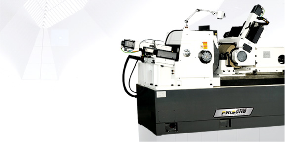
The grinding wheel of the centerless grinder MK1050A-CHL is installed on the grinding wheel spindle, as shown in Figure 1. One end of the grinding wheel spindle is equipped with a pulley A with a diameter of DA. The grinding wheel motor end is equipped with another pulley B with a diameter of DB. The grinding wheel spindle is driven by a grinding wheel motor through a belt. Pulley B is the driving wheel, pulley A is the driven wheel, and the linear velocities of the two pulleys are the same. The design of the grinding wheel motor adopts the domestically produced YX3-160L-4-B3 type, with a power of P=15kW, a rated speed of nD=1470r/min, and a voltage of 380V/50Hz. The motor is driven by a frequency converter, which uses Schneider ATV312 type frequency converter. The circuit diagram is shown in Figure 2. An analog voltage of 0-10V is input between AI1 and COM terminals to adjust the speed of the grinding wheel motor. The LI1 and+24V terminals are used to control the start and stop of the grinding wheel motor. 1) Method 1: Utilizing the built-in simulation spindle control function of FANUC system, assigning values through NC program, and connecting the analog voltage signal of interface JA40 to the frequency converter to achieve variable frequency speed regulation of the grinding wheel motor, thus achieving constant linear speed control of the grinding wheel. Firstly, set the relevant parameters. Due to the use of a motor with a rated speed of nD and 380V/50Hz for the grinding wheel motor. Set the parameter "maximum frequency" in the ATV312 frequency converter to 100Hz. When the analog voltage input to the frequency converter is+10V, the grinding wheel motor will operate at a frequency of 100Hz, that is, at a speed of 2nD. Considering the reduction ratio of DB: DA between the grinding wheel spindle and the grinding wheel motor, the parameters No.3741 and No.4020 in the FANUC system are set to nm. The maximum speed of the spindle motor is nm=2nDB/DA.
No.3741=nm, The spindle speed of the low-speed gear when the command voltage is 10V.
No.4020=nm, The maximum speed of the spindle motor.
No.8133#5=1, Parameter SSN, set 1 to simulate the spindle, without using spindle serial output.
No.3717=1, The parameter ISI, set to 1, indicates the use of the spindle connected to amplifier 1.
No.3716#0=0, Parameter A/Ss, set to 0 to indicate that the type of spindle motor is a simulated spindle.
No.3735=0, Minimum clamping speed.
No.3736=nm, Maximum clamping speed.
No.4056=100, Transmission ratio, 100 represents 1:1.
No.3706#6=1,No.3706#7=1, Determine the polarity of the spindle speed command output.
The NC program is written as follows:% O022
N10 #520=#702*60*1000/3.14/#638
N20 M03 S#520
N100M30% macro variable # 702 represents the constant linear speed of the grinding wheel, which is set by the user according to the processing requirements.
Macro variable # 638 represents the current diameter of the grinding wheel. As the grinding wheel dressing action is executed, the current diameter of the grinding wheel will change with the dressing amount.
Macro variable # 520 represents the current spindle speed of the grinding wheel, which is calculated. Improve the control method to address the shortcomings of Method 1. Still using interface JA40 to connect analog voltage signals to the frequency converter, achieving variable frequency speed regulation of the grinding wheel motor, but using PMC to control the spindle rotation. This method does not require assigning values through NC programs, but directly assigns values through PMC programs to achieve constant linear speed control of the grinding wheel. When the machine tool is turned on and running, there is no need to first run the simulated spindle speed assignment program in the NC program, and the grinding wheel can operate.
All constant line speed operations will be executed in the PMC program. The user's requirement for setting the linear speed of the grinding wheel is input through macro variable parameter # 702, and the current diameter of the grinding wheel is also stored in macro variable parameter # 638. We first need to read the relevant macro variable parameters into the PMC program address. Write the PMC program as shown in Figure 4.
Jiangsu Phisong CNC machine CO.,LTD.

0510-81025370
15961704177

wxmachine@sina.com

No. 18 Hehui Road , Huishan district of Wuxi City, Jiangsu, China
© 2023 Jiangsu Phisong CNC Equipment Co., Ltd. All rights reserved Su ICP Registration No. *******