


Dynamics
Elimination method of "reverse drag" in centerless grinding machine processing
Release time:2020-12-16
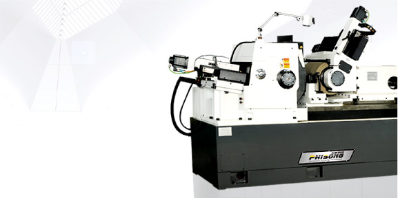
CenterlessGrindingMachine(无心磨床),It is a type of grinding machine that does not require the axis positioning of the workpiece for grinding. It mainly consists of three mechanisms: grinding wheel, adjustment wheel, and workpiece support. The grinding wheel actually performs the grinding work, the adjustment wheel controls the rotation of the workpiece, and controls the feed speed of the workpiece. As for the workpiece support, it supports the workpiece during grinding. There are several ways to cooperate with these three mechanisms, except for stopping grinding, and the principle is the same.
Due to the small diameter of the processed parts, it is required that the speed of the guide wheel be relatively low in order to reduce the output voltage and load capacity of the thyristor device. In actual production, due to rough material exceeding the tolerance or other reasons, the amount of grinding per unit time increases, and the grinding force generated by the grinding wheel grinding the workpiece will cause the speed of the guide wheel to change. This phenomenon is called "reverse drag". Due to the "reverse drag" of the guide wheel, when the speed of the guide wheel is adjusted to 20r/min, the actual speed of the guide wheel during processing will increase to 10r/min with the grinding speed of the grinding wheel. When the grinding wheel exits the grinding process, the speed of the guide wheel will decrease to 0. The speed fluctuation reaches 200%, seriously affecting product quality and safety production. Actual motor current measurement: During the grinding process, the current decreased from normal 1.5A to 0A, and then rebounded to 1.5A. By observing with an oscilloscope, it can also be seen that the thyristor has been turned off during the grinding process of the grinding wheel, and the motor is completely out of control.
After inspection, all links of the speed control system are working normally, and the speed of the guide wheel can be continuously adjusted under light load. The reason for the thyristor turning off during the grinding process is that the motor is "reversed" and the speed increases, the current decreases, and the given voltage of the thyristor device is lower than the motor terminal voltage, causing the thyristor to turn off. At this point, the motor is actually running in the generator state.
In order to eliminate the impact of "reverse drag", the machine tool factory has specially designed a loading device, which requires adding components to the machine tool, making the structure more complex. From the above analysis, it can be seen that the motor is in the running state of the generator during "reverse drag". If the principle of reversible system operation is applied, a current channel is provided at this time to reverse the armature current. Then the motor can be braked at a speed higher than the given speed (referring to the speed of the guide wheel motor during normal grinding, usually when the diameter of the grinding part is below 25mm, the motor speed is below 50r/min) to achieve stable speed. We adopt the method of parallel connection of an electric motor at both ends of the DC motor, so that the guide wheel provides braking current to the motor in the generator state when the speed is higher than the given speed, limiting the increase in speed and effectively eliminating the influence of "reverse drag" on the motor, keeping the speed basically stable. In addition, we connect switches in series in the resistor circuit to ensure that the resistor is only connected during low-speed grinding of the guide wheel, in order to prevent energy consumption by the resistor at other times.
By taking this measure, not only can the speed of the guide wheel be maintained stable, but the machining capacity of the machine tool can also be improved (increasing the amount of grinding). Therefore, this method can be used to eliminate "reverse drag" for DC motors operating at low speeds. Due to the fact that the resistor is connected in parallel at both ends of the motor armature winding, i.e. directly connected to the output terminal of the thyristor rectifier voltage, it is not possible to simply pursue the braking effect and reduce the resistor, as this will result in excessive resistor shunt during normal operation. The resistance value should be adjusted from large to small. We use RX-20, a resistor with a power of 10W, and a normal operating current value of 1A, which has little effect on the 20A thyristor; When braking, the motor current is also 1A, which has no effect on the motor. This circuit has a good effect on machining shaft parts with a diameter of less than 25mm. If the diameter of the part is large and the speed of the guide wheel is required to be high, the resistance consumption will be high, and it is not suitable for use.
Jiangsu Phisong CNC machine CO.,LTD.

0510-81025370
15961704177

wxmachine@sina.com

No. 18 Hehui Road , Huishan district of Wuxi City, Jiangsu, China
© 2023 Jiangsu Phisong CNC Equipment Co., Ltd. All rights reserved Su ICP Registration No. *******